There is one (1) pneumatic driven pump to achieve the Hydraulic pressure.
The pump has an internal start stop valve, when the air has been vented from the pilot port the pump will stop at the end of the stroke.
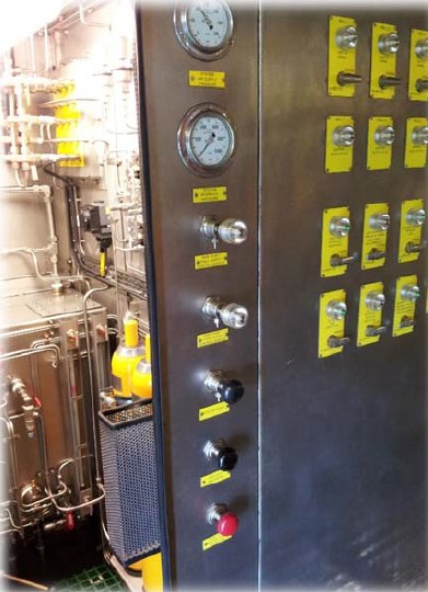
All pressure levels can be read out on pressure gauges installed on the front-side of the control panel.
A safety relief valve protects the pump and the system. The relief valve is sized for the full flow capacity Of the pump.
The hydraulic energy is stored in two (2) hydraulic accumulators, mounted in the panel (max working pressure 6500PSI).
The accumulators will also be used for pulsation damping.
The pressure generated by the system is controlled via High Pressure Pilot. The High Pressure Pilot will start and stop the pump.
The local pump start/stop/bypass functions are activated by two (2) ball valves.
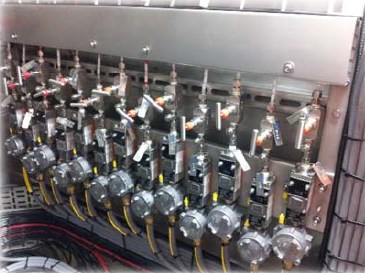
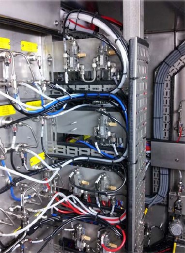
All components, which require maintenance or calibration, can be isolated with manual valves.
The reservoir has been designed in such a way that the return oil will enter the degassing section.
A filler breather cap is installed to protect the reservoir against overpressure.
The level of the degassing reservoir and the main reservoir is indicated on the individual level gauges inside the cabinet.
A level switch is installed at 20% of the clean reservoir; it will generate a pump stop and a signal to platform logic if the level will come below 20%.