The system has been designed to operate nine (9) production wells, seven (7) installed and two spare.
Each well consist of a Surface Controlled Subsurface Safety Valve (SCSSV), Surface Safety Valve (SSV) and Shut Down Valve (SDV).
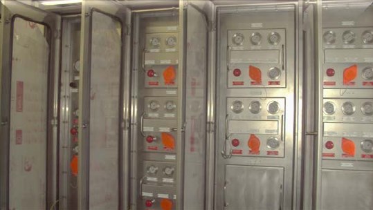
The following valves are also equipped with a manual (shutdown) valve at the front of the panel:
The SCSSV, SSV and SDV.
The Hydraulic Well Head Control Panel operates at four (4) pressure levels:
480 bars (called VHP header in the further document) for the 9 x SCSSV.
280 bar (called MHP header in the further document) for the 9 x SSV and 9 x SDV valves.
150 bar (called HP header in the further document) for the field loop, consisting out of 9 x ROCV, 10 x ESDV, 14 x SDV and 4 BDV.
6 bar (called LP header in the further document) control pressure.
Each pressure level is equipped with two (2) dedicated electric driven pumps (A & B) to achieve the required pressure,except for the LP header, which generated (reduced) from the HP header. This will be done by means Of two (2) pressure regulators; remark: “only one in service at all time!!”
Each pressure level is equipped with two (2) dedicated accumulators for energy storage generated by the pumps.
The VHP header is equipped with 5 liter bladder accumulators, with a nitrogen precharge of 357, 2 bars.
The MHP header is equipped with 35 liter bladder accumulators, with a nitrogen precharge of 170, 9 bars.
The HP header is equipped with 35 liter bladder accumulators, with a nitrogen precharge of 98, 9 bar. And the LP header is equipped with 2, 5 liter bladder accumulators, with a nitrogen precharge of 3 bar.
All accumulators are installed inside the wellhead panel. The pre-charge pressure must be checked at least once per year and if necessary charged again.
The pressures generated by the system are transmitted via Pressure transmitters to the PCS and ESD. Each header is equipped with two (2) transmitters and each pump set is equipped with one (1) transmitter for start/stop control.